Tasmota for SM-PW701E devices
Among the many WiFi controllable smart power switches, various vendors sell models named SM-PW701E. Like the Sonoff S20 devices, they contain an ESP8266 (or alike) module and can thus be reprogrammed with your own firmware. Unfortunately, the model described here doesn’t make this easy: the necessary pins to program the ESP8266 aren’t connected to anything.
The image below shows the location of the necessary signals to flash the module:
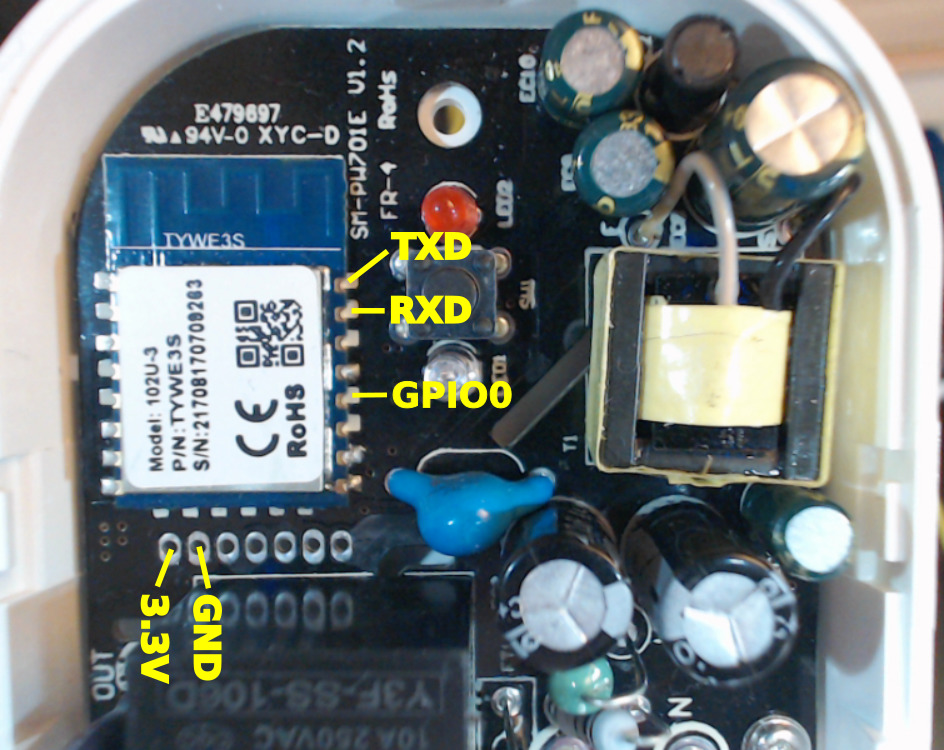
The pinout of the TYWE3S module is identical to an ESP-12F module (without its bottom row signals). Neither the UART signals, nor GPIO0 are routed to the unpopulated header. In fact, they aren’t even soldered onto the pads of the PCB. It seems, as if the header is only there for testing: in addition to the voltage pins it only contains the three GPIO pins 4, 12 and 13. The remaining two pins are definitely not connected to the ESP module. I didn’t check whether they are connected to something else on the board.
The following code fragment for kModulesList in the sonoff_template.h
file of the Sonoff-Tasmota software shows the assignment of button, LEDs
and relay:
{ "SM-PW701E",
    0,                  // GPIO0
    0,                  // GPIO1
    0,                  // GPIO2
    0,                  // GPIO3
    GPIO_LED1_INV,      // GPIO4 Blue Led
    0,                  // GPIO5
    0,                  // GPIO6
    0,                  // GPIO7
    0,                  // GPIO8
    0,                  // GPIO9
    0,                  // GPIO10
    0,                  // GPIO11
    GPIO_REL1,          // GPIO12 Red Led + Relay
    GPIO_KEY1,          // GPIO13 Button
    0,                  // GPIO14
    0,                  // GPIO15
    0,
    0                   // ADC0 A0 Analog input
  },
Don’t forget to add a corresponding enum value to supported_modules
and kNiceList.